Alexandr Poltavsky
Software Developer
Location: Russia, Moscow
poltavsky.alexandr@gmail.com
Blog
Github
Shadertoy
Twitter
Introducing DFAA antialiasing algorithm
Update! There will be a new post with more correct implementation of DFAA. The current version isn't precise in all cases, it can be made much better.
Aliasing is a longstanding problem in computer graphics. To date a lot of different algorithms have been developed. These are just some of them: SSAA, MSAA, CSAA, MLAA, FXAA etc.
In graphics we have to deal with spatial aliasing. Here is a depiction (sorry for quality):
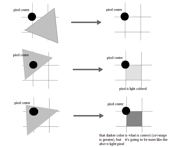
You can see from the second and third examples in the figure that having proper pixel color can provide important information to our brain. This becomes even more crucial in VR. Thinking about aliasing in that direction got me to an interesting idea: what if we somehow store the geometry information of the polygon and reuse it in a pixel shader?
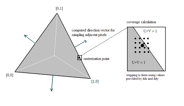
After iterating through a number of options (store edge equations in some form) I realized that all we need is already available to us: derivatives coupled with Barycentric coordinates. I have already been toying with the [0,0], [1,0], [0,1] coordinate system in the past, and I know other people also used it for things like wireframe rendering.
First Step: Barycentric Coordinates
So, the first step in the DFAA algorithm is to assign the Barycentric coordinate system to the polygon. For non-indexed geometry this can be done with the vertex id. Alternatively you can always provide your own uv's, or use a buffer with 0,1,2 values for each vertex. HLSL code looks like this:
//Barycentrics
static float2 uv01[] = { {0,0}, {1,0}, {0,1} };

//in SM > 3.0 we use SV_VertexID
out.uv01 = uv01[ 3 * frac( SV_VertexID/3 ) ];

//or in SM <= 3.0 we use a generated buffer with 0,1,2 values for each vertex
out.uv01 = uv01[ uvid ];
For indexed geometry SV_VertexID generally won't work (you can try, especially if your vertices are in strips), so we need to either use a geometry shader or generate a buffer with 0,1,2 mapping. Geometry optimized as triangle fans won't do well (we'll end up having duplicate 0 or 1 or 2). Here's an example how you can generate such a buffer:
auto uvid_buffer = generate_uv_ids<float>( index_buffer, tris_count*3 );
Here is a sample how it works: Ideone. The code: Github
Second Step: Pixel Shader
The pixel shader part is done in two steps. In the first step we use the provided Barycentrics (that should be used with noperspective modifier) and compute two values: direction of sampling and coverage. Picture here will make it easy for you to understand the code of the shader.
Here is the first pass shader function:
static const float pi2 = 2*3.1415926;


//Implementation of the DFAA algorithm
//should be fed with a [0,0],[1,0],[0,1] UV
//returns one byte with packed direction and coverage


static float rad = 0.5; //rad - radius of sampling, 0.5 means half-pixel
static float steps = 3; //(steps+1)^2 - total number subsamples for coverage computation

//uv01 should be with 'noperspective' modifier (though it seems to have no impact)

float DFAA( float2 uv01 ) {

  float2 uvdx = ddx( uv01 );
  float2 uvdy = ddy( uv01 );

  float area=0;

  //compute non-coverage

  for(float y=0; y<=steps; y++) {
    for(float x=0; x<=steps; x++) {
      float2 dxdy = float2( 2*rad*x/steps - rad, 2*rad*y/steps - rad );
      float2 edge = uv01 + uvdx * dxdy.x  + uvdy * dxdy.y;
      // if we are out of the triangle - increase by one the non-coverage
      if( edge.x < 0 || edge.y < 0 || ( edge.x + edge.y ) > 1 ) area++;
    }
  }

  //get actual coverage
  area = 1 - area / pow(steps+1, 2);

  //the next big step is to compute the direction of sampling
  //we get the inverse matrix and compute the edge vectors of the polygon
  //then we break the polygon into three independent parts by medians
  //and get the right edge, then rotate it by 90 degrees

  float2 dir;
  float2 uvdx2 = normalize( uvdx ), uvdy2 = normalize( uvdy );

  //matrix inverse
  float det = 1 / ( uvdx2.x * uvdy2.y - uvdx2.y * uvdy2.x );
  float2 xydu = det * float2( uvdy2.y, -uvdx2.y );
  float2 xydv = det * float2( -uvdy2.x, uvdx2.x );

  //choosing the edge using triangle medians
  float2 z = float2( xydv - xydu );
  if( uv01.y > uv01.x && (uv01.y+2*uv01.x) < 1 ) dir = float2( -xydv.y, xydv.x );
  else if( uv01.x > uv01.y && (uv01.x+2*uv01.y) < 1 ) dir = float2( xydu.y, -xydu.x );
  else dir = float2( z.y, -z.x );

  //so that we don't have to worry about winding of uv's
  dir = cross( float3(xydu, 0), float3(xydv, 0) ).z > 0 ? dir : -dir;

  //encode direction as an angle
  float dir_atan = atan2( dir.y, dir.x );
  float dir_angle = ( dir_atan < 0 ? dir_atan + pi2 : dir_atan ) / pi2;

  //pack into one byte
  float dfaa =  ( floor(15*dir_angle)*16 + 15*area ) / 255;

  return dfaa;

}
As you see, all we need is 1 byte of information per pixel. That's the cost of this method. After getting that information in a framebuffer we need to make a fullscreen pass to perform antialiasing. We do that by lerping between two colors: current and the one sampled along the computed direction and using computed coverage info.
//pixel to display and packed DFAA in alpha
sampler tex0 : register(s0);

static const float pi2 = 2*3.1415926;

//defines used by DFAA
#define dfaa_screen_texture tex0
#define dfaa_tex2D tex2D

//DFAA: performs fetch, unpack and lerp
float3 DFAA( float2 screenxy ) {

  float4 color0 = dfaa_tex2D( dfaa_screen_texture, screenxy );
  float dfaa_packed = color0.a;

  //unpack
  float dir_angle = floor(255*dfaa_packed/16)/15;
  float2 dir = float2( cos( dir_angle * pi2 ), sin( dir_angle * pi2 ) );
  float area = frac(255*dfaa_packed/16)*16/15;

  float2 sdx = ddx( screenxy );
  float2 sdy = ddy( screenxy );

  float4 color1 = color0;

  //only do fetch if necessary (edge pixels)
  if( area > 0 && area < 1 )
    color1 = dfaa_tex2D( dfaa_screen_texture, screenxy + sdx*dir.x + sdy*dir.y );

  return lerp( color1, color0, area ).rgb;
}
So that's it. I provide a GitHub repository with the two pixel shaders. I also put there a small Windows demo and a RenderMonkey project. In the RenderMonkey project you have convenient knobs on the right to turn on/off DFAA and see the difference.
Here is a zoomed in screenshot of the DFAA at work.

It seems like that approach could also help improve shadow quality. Would be nice to see DFAA being used in real games.